ADVERTISEMENTS:
In this article we have compiled three main theories given by Coulomb for studying earth pressure. The theories are: 1. Coulomb’s Wedge Theory for Earth Pressure 2. Coulomb’s Theory of Active Earth Pressure 3. Coulomb’s Theory for Passive Earth Pressure.
1. Coulomb’s Wedge Theory for Earth Pressure:
Coulomb (1776) developed the wedge theory for determination of lateral earth pressure on a retaining wall. Unlike Rankine’s theory, which considers the equilibrium of a soil element, Coulomb’s theory considers the equilibrium of a sliding wedge of soil in the backfill that separates from the rest of the backfill above a failure plane.
The mass of soil in the backfill above safe/stable slope is unstable and it tends to slide as the wall moves away or toward the backfill. Coulomb stated that this wedge of soil moves outward (away from the backfill) and downward in the active case when the wall moves away from the backfill.
ADVERTISEMENTS:
While in Rankine’s theory, the failure plane is inclined at 45 + (ɸ/2) to the major principal plane at any point in the backfill where the soil reaches the state of plastic equilibrium, Coulomb’s theory states that the failure plane passes through the heel of the wall and its inclination with the horizontal should be determined by trial and error such that lateral earth pressure is maximum in the active case (active earth pressure) and minimum in the passive case (passive earth pressure).
Coulomb’s theory states that the total lateral earth pressure is equal to the reaction exerted by the retaining wall when the wedge of soil tends to slide and acts at an angle 8 with the normal to the back of the wall. It may be noted that Coulomb’s theory takes into account the roughness and inclination of the back of the wall and also the inclination of the backfill surface. Coulomb’s theory was developed much earlier to Rankine’s theory.
As Rankine’s theory is much simpler than Coulomb’s theory, it has become more popular among engineers, although it is less accurate with several simplifying assumptions. Coulomb’s theory gives more accurate values of lateral earth pressure, and all variables affecting lateral earth pressure are duly considered unlike in Rankine’s theory.
Coulomb’s Theory for Active Earth Pressure for Cohesionless Backfill:
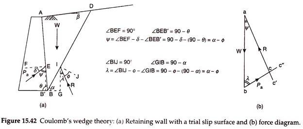
As per Coulomb’s theory, a wedge of soil above a failure plane moves outward and downward in the active case when the wall moves away from the backfill due to lateral earth pressure. Figure 15.42(a) shows a retaining wall of height H with a cohesionless backfill, with its surface inclined at an angle β with the horizontal. The back of the wall is inclined at an angle θ with the horizontal. Consider the failure plane BC at an inclination of α with the horizontal.
ADVERTISEMENTS:
The wedge of soil ABC tends to slide outward and downward away from the rest of the backfill. The wall resists the movement of the wedge and exerts a reaction Pa, inclined at an angle Δ with the normal to the wall, where Δ is the angle of wall friction. The magnitude of total active earth pressure is equal to Pa.
The total active earth pressure is determined in Coulomb’s theory by considering the equilibrium of the wedge of soil ABC.
The forces acting on the wedge are:
i. Weight (W) of the soil in the wedge of soil ABC, acting vertically downward.
ADVERTISEMENTS:
ii. The reaction (Pa) on the contact surface AB of the wall with the backfill, acting at an angle Δ with the normal to the back of the wall. As the wedge moves outward and downward, Pa acts inward and upward, opposing the movement of the wedge.
iii. The reaction (R) on the trial failure plane BC, which is the contact surface of the wedge with the rest of the backfill. The reaction R acts at an angle ɸ with the normal to the surface BC. This reaction acts upward and outward, opposing the movement of the wedge.
From, Fig. 15.42(a), angle of Pa with the vertical –
Ψ = θ – Δ ….(15.82)
ADVERTISEMENTS:
Similarly, from Fig. 15.42(a), angle of R with the vertical –
λ = α – ɸ …(15.83)
A trial value of α is assumed and the force diagram is constructed. Figure 15.42(b) shows the force diagram abc. A line ab is drawn parallel to the line of action of W, with the length ab equal to W to some scale. Now, a line bc’ is drawn parallel to the line of action of Pa, that is, at an angle (θ – Δ) with ab. Another line ac” is drawn parallel to the line of action of R, that is, at an angle (α- ɸ) with ab. The two lines bc’ and ac” intersect at point c, which completes the force diagram abc. The length of the line be gives the value of Pa to the scale of the force diagram for the assumed trial value of α.
The procedure is repeated for other failure planes, taking different trial values of α, and the corresponding values of Pa are determined. The maximum value of Pa, among the trial values, is taken as the active earth pressure. The corresponding trial failure plane is taken as the critical failure plane.
ADVERTISEMENTS:
The active earth pressure acts along the same line of action as Pa, but opposite in direction. To determine the point of application of Pa, a line is drawn from the centroid of the wedge of soil ABC parallel to the critical failure plane to intersect the back of the wall at point P, which is the approximate point of application of Pa.
Coulomb’s theory assumes that the failure surface is a plane surface, the actual surface being a curved surface. In the active case, however, the error involved in the estimation of Pa with a plane failure surface is found to be small. The angle of wall friction may be determined by conducting a shear box test with the wall material in the bottom half and the backfill material in the upper half of the shear box. The value of Δ is found to be in the range of ɸ/3 – 2ɸ/3.
Expression for Coulomb’s Active Earth Pressure:
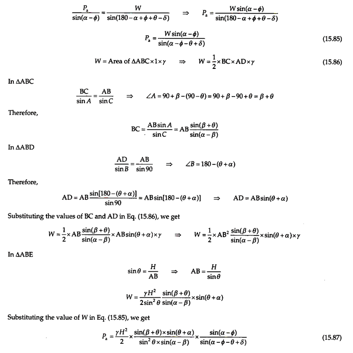
Referring to the force diagram shown in Fig. 15.42(b) and applying Lami’s theorem –
Pa/sin(α – ɸ) = W/sinC …(15.84)
In Δabc
Substituting this value of angle C in Eq. (15.84), we get –
The condition for maximum active earth pressure is obtained by differentiating Eq. (15.87) with respect to α and equating to zero –
dPa/dα = 0
The final expression for active earth pressure is given by –
Pp = Ka (γH2/2) …(15.88)
where
In Eqs. (15.88) and (15.89), H is the vertical height of the wall; θ the angle of back of the wall with horizontal; ɸ the angle of shearing resistance; Δ the angle of wall friction of the back of the wall; β the angle of backfill surface with horizontal; and γ the density of backfill material.
2. Coulomb’s Theory of Active Earth Pressure:
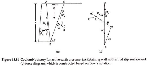
Figure 15.51(a) shows a retaining wall of height H, with a cohesive backfill, with its surface inclined at angle β with the horizontal. The back of the wall is inclined at an angle θ with the horizontal. Consider failure plane BD at an inclination of α with the horizontal.
The wedge of soil ABD tends to slide outward and downward always from the rest of the backfill in the active case. The wall resists the movement of the wedge and exerts a reaction Pa, inclined at an angle δ with the normal to the wall, where δ is the angle of wall friction. The magnitude of total active earth pressure is equal to Pa.
The total active earth pressure is determined in Coulomb’s theory by considering the equilibrium of the wedge of soil ABD.
The forces acting on the wedge for a cohesive backfill are as follows:
i. Weight (W) of the wedge of soil ABD, acting vertically downward.
ii. The reaction (Pa) on the contact surface AB of the wall with the backfill, acting at an angle δ with the normal to the back of the wall. As the wedge moves outward and downward, Pa acts inward and upward, opposing the movement of the wedge.
iii. The reaction (R) on the trial failure plane BD, which is the contact surface of the wedge with the rest of the backfill. The reaction R acts at an angle ɸ with the normal to the surface BD. This reaction acts upward and outward, opposing the movement of the wedge.
iv. The cohesive force, Cs, acting along the failure plane BD, that is, at an angle α with the horizontal in the upward and inward direction, resisting the movement of the wedge. Cs = cu × BD × 1 = cu × BD.
v. The cohesive force due to adhesion between the wall and the backfill, Cw, acting along the back of the wall, that is, at an angle of θ in the upward direction. Cw = cu × AB × 1 = cu × AB.
Angle of Pa with the vertical, Ψ = 90 – (90 – θ + δ) = 90 – 90 + θ – δ = θ – δ
Angle of R with the vertical, λ = 90 – (90 – α + ɸ) = 90 – 90 + α – ɸ = α – ɸ
A trial value of α is assumed and the force diagram is constructed. Figure 15.51(b) shows the force diagram abcde, representing the forces W, Cs, R, Pa, and Cw, using the forces in the clockwise order in the space as per Bow’s notation.
A line ab is drawn parallel to the line of action of W, with the length ab equal to W to some scale. From b, a line be is drawn equal in length to Cs to the same scale parallel to line of action of Cs, shown in Fig. 15.51(a). From a, a line ad is drawn equal in length to Cw parallel to the line of action of Cw. From point c, a line ce’ is drawn parallel to the line of action of R, that is, at an angle (α – ɸ) with the vertical. Another line de” is drawn from point d parallel to the line of action of Pa, that is, at an angle (θ – δ) with the vertical. The two lines ce’ and de” intersect at point e, which completes the force diagram abcde. The length of line de gives the value of Pa to the scale of the force diagram for the assumed trial value of α.
The procedure is repeated for other failure planes, taking different trial values of α, and the corresponding values of Pa are determined. The maximum value of Pa, among the trial values, is taken as the active earth pressure. The corresponding trial failure plane is taken as the critical failure plane. The active earth pressure acts along the same line of action as Pa, but opposite in direction. To determine the point of application of Pa, a line is drawn from the centroid, G, of the wedge of soil ABD parallel to the critical failure plane to intersect the back of the wall at point P, which is the approximate point of application of Pa.
3. Coulomb’s Theory for Passive Earth Pressure:
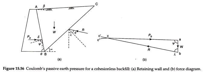
As per Coulomb’s theory, a wedge of soil above a failure plane moves inward and upward in the passive case when the wall moves toward the soil on the front side of the wall due to lateral earth pressure. Figure 15.56(a) shows a retaining wall of height H, with a cohesionless backfill, with its surface inclined at an angle β with the horizontal.
The back of the wall is inclined at an angle θ with the horizontal. Consider the failure plane BC at an inclination of α with the horizontal. The wedge of soil ABC tends to slide inward and upward. A pressure is exerted on the wall, which is the passive earth pressure Pp, inclined at an angle δ above the normal to the wall, where δ is the angle of wall friction.
The total passive earth pressure is determined through Coulomb’s theory by considering the equilibrium of the wedge of soil ABC.
The forces acting on the wedge are as follows:
i. Weight (W) of the wedge of soil ABC acting vertically downward.
ii. The reaction (Pp) on the contact surface AB of the wall with the backfill, acting at an angle Δ above the normal to the back of the wall.
iii. The reaction (R) on the trial failure plane BC, which is the contact surface of the wedge with the rest of the backfill. The reaction R acts at an angle ɸ above the normal to the surface BC. This reaction acts upward and outward, opposing the movement of the wedge.
A trial value of α is assumed and the force diagram is constructed. Figure 15.56(b) shows the force diagram abc. A line ab is drawn parallel to the line of action of W, with the length ab equal to W to some scale. Now, a line bc’ is drawn parallel to the line of action of P, that is, at an angle (θ – δ) with ab. Another line ac” is drawn parallel to the line of action of R, that is, at an angle (α – ɸ) with ab. The two lines bc’ and ac” intersect at point c, which completes the force diagram abc. The length of line be gives the value of Pp to the scale of the force diagram for the assumed trial value of α.
The procedure is repeated for other failure planes, taking different trial values of α, and the corresponding values of Pp are determined. The minimum value of Pp among the trial values, is taken as the passive earth pressure. The corresponding trial failure plane is taken as the critical failure plane. The final expression for Coulomb’s passive earth pressure is given by –
Coulomb’s theory assumes that the failure surface is a plane surface. The actual surface is found to be a curved surface, being either a logarithmic spiral or a circular arc. In the passive case, however, the error involved in the estimation of Pp is large when a plane failure surface is used for values of δ > (ɸ/3), which is the usual case. The value of Pp estimated is more than the actual value and is therefore on the unsafe side. Coulomb’s theory is therefore generally not used for the estimation of passive earth pressure.
Passive Earth Pressure by Friction Circle Method:
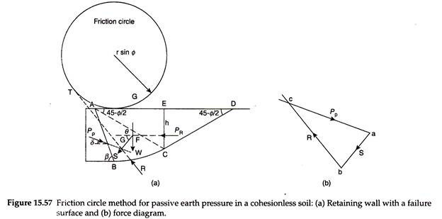
The assumption of a plane surface for failure surface in Coulomb’s theory leads to serious errors in the estimation of passive earth pressure. The friction circle method considers the failure surface as a combination of an arc of a circle and a tangential straight line.
Figure 15.57 shows a retaining wall of height H with a horizontal cohesionless backfill with a horizontal surface.
The failure surface BCD consists of an arc of a circle BC of radius r and a tangent CD. Zone CDE of the backfill is assumed to be in a passive Rankine’s state. The effect of zone CDE is considered in the form of a Rankine’s passive earth pressure, PR.
The soil in zone ABCEA is subjected to the following forces:
1. The weight, W, of zone ABCEA of the backfill. W = Area ABCEA × 1 × γ = γA. It acts vertically downward through the centroid of area ABCEA.
2. The Rankine’s passive earth pressure from zone CDE of the backfill will be –
It acts horizontally at a height of h/3 above point C.
The resultant, S of W and PR, can be obtained as –
It acts at an angle θ, given by –
tanθ = W/PR …(15.94)
The lines of action of W and PR are drawn that intersect at point F. From point F, a line is drawn at an angle θ with the horizontal, which is the line of action of S.
3. The passive earth pressure Pp, acting at an angle δ above the normal to the wall.
4. The reaction R, acting at an angle ɸ with the normal to the tangent to the curve. The reaction R is actually tangential to a friction circle of radius rsin ɸ with the same center as the center of the arc BC.
Hence, the backfill ABCE is in equilibrium under the action of the three forces Pp, R, and S. From the principles of mechanics, it is known that when a body is in equilibrium under the action of three forces, the three forces are concurrent.
The procedure for determination of passive earth pressure is as follows:
1. Draw the lines parallel to Pp and S to intersect at point G. The reaction R should also pass through point G. The friction circle is drawn with rsin ɸ as the radius and O as the center. A line GT is drawn from point G, tangential to the friction circle. The line GT represents the line of action of R.
2. To construct the force diagram abc, a line ab is drawn of length equal to S to some scale at an angle θ with the horizontal. Two lines are drawn from points a and b parallel to the directions of Pp and R. The point of intersection of these two lines is c.
3. The length of line ca gives the passive earth pressure Pp to the scale of the force diagram.
The value of Pp obtained is applicable to the trial failure surface BCD. The procedure is repeated with other failure surfaces with different radii. The minimum value of Pp obtained among all the trials is taken as the passive earth pressure.
