ADVERTISEMENTS:
In this article we will discuss about the design features and types of soil samplers.
Design Features of Soil Samplers:
The basic tool used for the collection of undisturbed soil samples from test pits or boreholes at required depth is known as a soil sampler.
The fundamental requirement of a sampling tool is that when it is forced into the ground, it should cause as little displacement, remolding, and disturbance to the soil as possible.
ADVERTISEMENTS:
The following design features of the sampling tool control the degree of disturbance:
1. Cutting edge.
2. Inside-wall friction.
3. Non-return valve.
ADVERTISEMENTS:
4. Recovery ratio.
1. Cutting Edge:
Cutting edge is the beveled and sharp edge at the bottom of the soil sampler. It may be an integral part of the soil sampler or a separate cutting bit may be screwed to the bottom of the sampler. It mainly facilitates driving of the soil sampler through the soil.
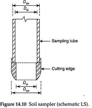
A typical cutting edge shown in Fig. 14.10 should have the following design features:
ADVERTISEMENTS:
The internal diameter of the cutting edge (Dci) should be slightly less than the internal diameter of the sampling tube (Dsi) to give inside clearance (Ci) (see Fig. 14.10).
The inside clearance does the following:
a. Allows for elastic expansion of the soil as it enters the sampler.
ADVERTISEMENTS:
b. Reduces the frictional drag on the soil sample from the wall of the sampler, which otherwise causes disturbance to the sample.
c. Helps to retain the soil sample.
Inside clearance is given by –
where Dsi is the inside diameter of the sampling tube and Dci is the inside diameter of the cutting edge.
ADVERTISEMENTS:
ii. Outside Clearance:
Outside clearance (Co) is the gap between the outer surface of the cutting edge and the outside surface of the sampling tube. Outside clearance prevents frictional drag between the outside surface of the sampling tube and the walls of the borehole or and hence facilitates easy driving and withdrawal of the sampler and also prevents damage of the sampler. The outside diameter of the cutting edge should be slightly more than that of the sampling tube to get the outside clearance.
Outside clearance is, therefore, defined by –
where Dco is the outside diameter of the cutting edge and Dso is the outside diameter of the sampling tube. The outside clearance should not be much greater than the inside clearance.
The outside clearance, the wall thickness of the sampler, and the inside clearance together influence the displacement caused to the natural soil during collection of the soil sample. The more the sum of these three, the greater will be the soil displacement and the more will be the degree of disturbance caused to the soil sample. This is expressed in the form of area ratio (Ar) and is defined as –
The area ratio should be kept as low as possible, consistent with the strength requirements of the sampling tube as well as the inside and the outside clearance requirements. Its value should not be greater than 20% for stiff formations and 10% for soft sensitive clays. Where it is not possible to provide sufficient inside clearance, piston sampler should be preferably used.
2. Inside-Wall Friction:
The inside-wall friction should be minimized for minimizing the disturbance of the sample by the following actions:
i. Provide suitable inside clearance.
ii. Provide a smooth finish to the sampling tube.
iii. Oil the inside surface of the sampling tube properly.
3. Non-Return Valve:
The valve should have a large orifice to allow air and water to escape quickly and easily when driving the sampler.
4. Recovery Ratio:
It is defined as the ratio of length of the sample within the sampling tube to the depth of penetration of the sampler during sampling. Thus, recovery ratio (Rr) is expressed by –
Rr = L/H …(14.4)
where L is the length of the sample within the tube and H is the depth of penetration of the sampling tube.
For satisfactory undisturbed sampling, when excess soil is prevented from entering the tube, the recovery ratio should be between 96% and 98%.
Types of Soil Samplers:
On the basis of area ratio, soil samplers are classified into the following types:
i. Thin-wall samplers.
ii. Thick-wall samplers.
Thin-wall samplers are the samplers in which the wall thickness of the sampling tube is less than 2.5% of the diameter. In other words, thin-wall samplers are those for which the area ratio is less than or equal to 10%. Samplers for which the area ratio is more than 10% are known as thick-wall samplers.
Later studies have modified the definition of thin-wall samplers to include the effect of cutting edge on sample disturbance. Accordingly, thin-wall samplers may be defined as those with an area ratio less than 20% when the sampler has a suitably designed cutting edge. Thick-wall samplers are those with an area ratio more than 20%.
Based on the sampler design and use, soil samplers are classified into the following types:
1. Open-tube sampler.
2. Standard split-spoon sampler.
3. Stationary piston sampler.
4. Rotary sampler.
5. Scraper bucket sampler.
1. Open-Tube Sampler:
The open-tube samplers are the simplest type of samplers for collection of undisturbed samples. They are thin-wall tube samplers made of seamless steel and are also known as thin-wall Shelby tube samplers. The bottom of the tube is sharpened and beveled, which acts as a cutting edge. The upper portion of the sampler has threads on the inside surface to enable the sampler to be attached to the bottom of the drill rod.
The most commonly used tube samplers are 5.08-7.62 cm in diameter (2-3 in.) and 60.96-76.2 cm (2-2.5 ft) in length. However, the use of tubes 10-15 cm (4-6 in.) in diameter has increased within the past two decades.
The use of large-diameter tubes has the advantage that it is possible to cut four small-diameter triaxial specimens (3.8 cm, i.e., 1.5 in. diameter) from the same level of the sampler. This is extremely important in residual soils, where the engineering properties vary considerably with depth.
The U.S. Army Corps of Engineers recommends the use of 12.5-cm- (5 in.-) diameter tubes in cohesive soils and shallow deposits of cohesionless soils. In the deeper cohesionless deposits, the use of 7.5-cm-diameter tubes is recommended, since the penetration resistance of the larger tubes exceeds the pushing capacity of the commonly used drilling rigs. The area ratio of the sampler is below 15% and the inside clearance is between 0.5% and 3%.
The procedure for collection of soil samples from a bore hole using open-tube sampler is as follows:
i. The sampler is attached to the bottom of the drill rod and is lowered to the bottom of the bore, where the undisturbed sample is to be collected.
ii. It is then driven into the soil, with fast and smooth strokes of careful hammering. Erratic pressure, if applied during hammering, becomes a source of sample disturbance.
iii. After driving the sampler up to the required length (equal to the sampler length minus provision for waxing), the sampler is rotated twice completely to shear off the sample from its intact bottom and is then withdrawn.
iv. The tube is removed from the sampler head and its ends are sealed with molten wax before transportation.
v. The sampler head is provided with vents at top to permit water to escape when sampling under water.
vi. It is also provided with a check valve to help retain the sample when withdrawing the sampler.
Shelby tube samplers are commonly used for collection of samples in fine-grained soft soils. The presence of obstructions to the sampler during driving, in the form of gravel or stones, cramps the beveled bottom edge and causes disturbance to the sample collected. The Shelby tube samplers are, therefore, unsuitable for hard or dense gravelly soils.
2. Standard Split-Spoon or Split-Barrel Sampler:
It is the most commonly used sampler for obtaining undisturbed soil samples. It is also known as split-barrel and split-tube sampler. A split-spoon sampler is also used to conduct SPT in the borehole. When the SPT is conducted, the soil sample simultaneously enters the sampler by the end of the test, which is then withdrawn and taken to the laboratory.
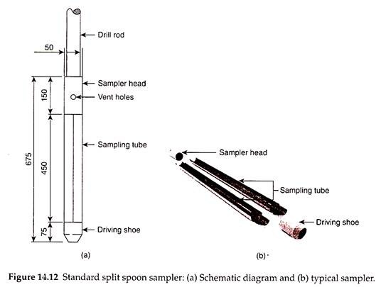
The standard split-spoon sampler consists of the following [Fig. 14.12(a)]:
i. A driving shoe made of 7.5-cm-long tool steel at the bottom.
ii. A 45-cm-long steel tube, split into two halves longitudinally, as shown in Fig. 14.12(b).
iii. A coupling or sampler head at the top of the tube, about 15 cm long.
The inside diameter of the steel tube is 3.8 cm (1.5 in.) and the outside diameter is 5.08 cm (2 in.). The coupling head is provided with a check valve and four venting ports of 1-cm diameter to improve sample recovery. In some split-spoon samplers, a separate sampling tube of 3.8-cm internal diameter is provided.
Following is the procedure for the collection of soil samples using standard split-spoon sampler:
i. After the borehole has been made, the sampler is attached to the bottom of the drill rod and lowered to the bottom of the hole.
ii. The sampler is forced into the soil by repeated blows of a drop hammer.
iii. The sampler is driven to the required length, taking care not to overstress the sample, and is then withdrawn.
iv. The split tube is separated after removing the shoe and the coupling, and the sampling tube with sample is taken out.
v. The sampling tube containing sample is then placed in a container, sealed, and transported to the laboratory.
vi. In the samplers with separate a 3.8-cm-diameter tube inside the split barrel, the tube is taken out, waxed on both ends, and transported to the laboratory.
vii. If the soil encountered in the borehole is fine sand below the water table, the sample recovery becomes difficult. For such soils, a spring core catcher device is used to aid recovery. As the sampler is lifted, the springs close and form a dome to retain the sample.
viii. While taking samples, the water level in the borehole should be always maintained higher than the GWT to prevent quick conditions.
3. Stationary Piston Sampler:
A piston sampler consists of two parts – (a) a sampler cylinder and (b) a piston system. The piston rod is 30 cm (12 in.) in diameter at the bottom end and fits easily inside the hollow drill rod.
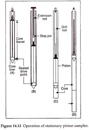
Figure 14.13 illustrates the operation of stationary position sampler. For obtaining a sample, the bottom of the piston is brought flush with the cutting edge of the sampler and the sampler is lowered into the borehole. When the sampler reaches the bottom of the hole, the piston rod is held fixed relative to the ground surface and the thin-wall tube is pushed into the soil by hydraulic pressure or mechanical jacking. The sampler is never driven. The sampling tube is pushed to the required depth and then the drill rod along with the whole sampler is withdrawn.
The piston prevents water and dirt from entering the tube during the lowering operation. When the sampling tube is pushed into the soil, keeping the piston fixed in position, a negative pressure is developed above the sample, which holds back the sample during withdrawal.
The stationary piston sampler is used for sampling soft-to-stiff cohesive soils. The quality of samples obtained is excellent and the probability of obtaining a satisfactory undisturbed sample is high. The use of piston enables a high recovery ratio for the soil sample, but at the same time, prevents recovery ratios higher than 100%, preventing entry of excess soil into the sampler.
4. Rotary Sampler:
The rotary samplers are double-tube samplers with a removable thin-wall tube, known as liner, inside an outer tube provided with a cutting bit. The rotary sampler has an outside diameter of 6.35-19.7 cm (3.5-7.75 in.) and a length of 61 cm (24 in. or 2 ft). The outer tube with the cutting bit is rotated and pushed down into the soil for the required length and the sample enters the liner. The inner tube, that is, the liner, provided with a smooth cutting shoe, remains stationary and the sample cut by the rotating outer tube slides into the liner. The sample is thus received in the liner.
Rotary samples can be used for collection of undisturbed samples in stiff-to-hard clays, silts, and sands with some cementation and also in soft rock. The sampler is, however, unsuitable for gravelly soils and loose cohesionless soils.
5. Scraper Bucket Sampler:
Sampling with a standard split-spoon sampler becomes difficult if the soil contains pebbles. Even if the sampler is fitted with a spring core catcher, the pebbles interfere with the springs and obstruct their closure. A scraper bucket sampler may be helpful for the collection of undisturbed samples in such soil deposits. However, it is possible to collect only disturbed samples using a scraper bucket sampler. The sampler is also useful to obtain samples of cohesionless soil below GWT.
The scraper bucket sampler contains a vertical slit at its upper portion and a driving point at its bottom. As the sampler is rotated, the scrapings of the soil enter into the sampler cylinder through the vertical slit. When the sampler is filled with the scrapings, it is lifted up and collected into a separate container. Although the sample is thoroughly disturbed, it still represents the soil at exact depth from where it is collected.


Comments are closed.