ADVERTISEMENTS:
In this article we will discuss about:- 1. Introduction to Well Foundations 2. Caissons and Its Types 3. Shapes 4. Components.
Introduction to Well Foundations:
Well foundations are one of the types of deep foundations that provide a solid and massive foundation typically for bridges and heavy structures. Well foundations are also useful for transmission line towers, where uplift loads are large. In earlier practice, well foundations were constructed with stone or brick, but today they are mostly of reinforced concrete. The advantages of well foundations are that they are monolithic and rigid, being a massive substructure. They have better lateral load resistance than pile foundations. Well foundations can also be conveniently installed in a boulder stratum as well.
Well foundations had their origin in India and have been used for hundreds of years for providing deep foundations for important buildings and bridges. Many Mughal monuments, including the famous Taj Mahal and several bridges, were supported on well foundations. The largest well used in the world in the early part of 20th century is the 73.8-m deep caisson provided for the San Francisco Oakland Bridge, in California. Well foundations have been used for most of the bridges in India. The main towers of the Howrah Bridge were provided with 31-m deep well foundations.
Caissons and Its Types:
Well foundations actually belong to one of the types of caissons. Caissons are box type foundations used to support bridges and other heavy structures and sunk into the ground under self-weight with additional weights applied at the top.
ADVERTISEMENTS:
Three types of caissons are commonly used, which are as follows:
1. Open caissons.
2. Box caissons.
ADVERTISEMENTS:
3. Pneumatic caissons.
These type of caissons are described below:
1. Open Caissons:
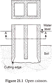
Open caissons, also called well foundations, are caissons in which the top and bottom of the caisson are open during construction. An open caisson may be circular, rectangular, or oblong in plan. Figure 21.1 shows an open caisson with double rectangular cross section. It has a cutting edge at the bottom, which is fabricated at the site along with the first segment of the shaft. When the well sinks by self-weight, the soil inside the shaft is dredged by suitable means, which aids further sinking into the ground.
The next segment of the shaft is then added to it. The process of sinking by self-weight, as well as by dredging, is continued till it reaches the required depth. The bottom of the well is then sealed with concrete, which also forms the base of the well foundation. The hollow shaft is filled with sand and a concrete seal is provided at the top, known as a top plug. Open caissons can be constructed up to any depth and the cost of construction is relatively low.
ADVERTISEMENTS:
The depth up to which the caisson is to be sunk depends on the loads on the caisson, the bearing capacity of the soil, skin friction resistance of the sides, and the minimum grip length to be used below the scour level.
The advantages of open caissons are as follows:
i. The caisson can be constructed to large depths.
ADVERTISEMENTS:
ii. The cost of construction is relatively less than other types of caissons.
The disadvantages of open caissons are as follows:
i. Progress of construction in boulder deposits is very slow.
ii. The concrete sealed under water is not very effective.
ADVERTISEMENTS:
iii. Inspection of the bottom of the well is not possible.
2. Box Caissons:
Box caissons are open at the top, but closed at the bottom, as shown in Fig. 21.2. It is first cast on land and then towed to the site, where it is sunk onto a previously leveled foundation base. Sinking of the caisson is facilitated by filling with sand, gravel, or concrete blocks inside the caisson. Box caissons are also called floating caissons, and are used where loads are not very heavy and a bearing stratum is available at shallow depth.
The advantages of box caissons are as follows:
i. The cost of construction of box caissons is low.
ii. It can be used where other types of caissons cannot be constructed.
The disadvantages of box caissons are as follows:
i. It is difficult to provide the foundation base below the water level, especially for deep excavations.
ii. Bearing capacity of the foundation base has to be properly assessed. Care has to be taken to protect the foundation base from scour.
3. Pneumatic Caissons:
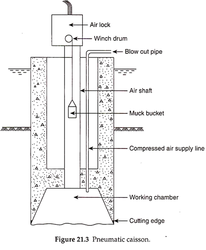
In pneumatic caissons, the internal air pressure of the closed chamber is kept high to prevent water from entering the chamber (Fig. 21.3). The working chamber is thus kept dry to facilitate skilled persons to work in the chamber. Air locks are provided at the top. The caisson is sunk under complete controlled conditions by skilled persons and supervisory staff in the working chamber. The working chamber is filled with concrete after the final depth is reached and sinking of the caisson is completed.
The advantages of pneumatic caissons are as follows:
i. There is a complete control over the sinking of the caisson, so that tilts and shifts can be detected immediately by the staff in the working chamber and corrective measures can be taken effectively.
ii. The bottom of the chamber can be sealed effectively as it is maintained under dry conditions.
iii. Obstructions to sinking, such as boulders, can be removed easily.
The disadvantages of pneumatic caissons are as follows:
i. Pneumatic caissons are costlier than other types of caissons.
ii. The depth of the caisson below the groundwater table is limited to about 35 m during construction, as the staff in the working chamber cannot withstand a pressure more than 35 t/m2.
Shapes of Well Foundations:
The following different shapes are used for well foundations, which have their own relative merits and demerits:
1. Circular.
2. Twin circular.
3. Square/Rectangular.
4. Double D.
5. Hexagonal/Octagonal.
Well foundations with different shapes of cross section are shown in Fig. 21.4.
These well foundations are discussed below:
1. Circular Wells:
Circular wells are simple in construction, easy to sink, and require minimum steining thickness due to lower flexural stresses than in other types. A circular well has the minimum surface area for a given weight, leading to greater sinking effort available. Circular wells possess high strength and are subject to low bending stresses due to the absence of sharp corners. They require only one dredger for sinking. As every point on the cutting edge is at a constant distance from the center of the dredge hole, chances of tilting of wells during sinking are less. Circular wells can be used for piers of single-line railway or road bridges.
If the length of the pier is long, the use of circular wells will become uneconomical, and also cause excessive obstruction to the flow. Circular wells offer less resistance to lateral loads. The maximum diameter of circular wells is generally limited to 9 m.
2. Twin Circular Wells:
Twin circular wells are advantageous when the depth of the foundation is small and the foundation soil has high bearing capacity. However, the main disadvantage is that there will be a differential settlement and tilting between the two wells with the loosening of sand between them or due to unequal sinking, even though the two wells are rigidly connected by a heavy top cap, unless the soil/rock is uniform.
3. Square/Rectangular Wells:
A Square/rectangular section is used for well foundations of small depth, of up to 8 m. For large-size piers or abutments, double rectangular wells with two dredge holes are used. The bending stresses are, however, very high in the steining due to sharp corners. A rectangular section is more economical than a square section.
4. Double-D Section Wells:
Double-D shape wells are an improvement over twin rectangular and twin circular wells and have two dredge holes each in the shape of the letter D, as shown in Fig. 21.4(g). The main advantage of double-D wells is their high lateral stability. When the size of the pier or abutment is large and cannot be accommodated on a single circular well economically, double-D wells will become the most economical and commonly used alternative shape.
They are easier to sink than double rectangular or octagonal wells but require larger sinking effort. The dimensions of the double-D section wells are so determined that the length and width of the dredge holes are almost equal.
The disadvantage of the double-D wells is that the bending moments are large on the steining, particularly on the junction wall between the two dredge holes. The well is prone to more tilting due to unequal width and length of the section.
5. Hexagonal/Octagonal Wells:
Hexagonal/octagonal wells have the advantage that the sharp corners present at the junction wall between the two dredge holes of a double-D well are eliminated, reducing the bending stresses in the steining. However, the surface area is more than that in a double-D section well, which increases the resistance to sinking. Concreting is also more difficult in steining. Double hexagonal/octagonal sections accommodate the full width of the bridge more economically than single sections.
Components of Well Foundation:
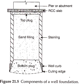
The various components of a well foundation, as shown in Fig. 21.5, are as follows:
1. Well Curb:
The well curb is designed to support the weight of the well. Additional loads that need to be considered in the design of a well curb are sand blows and blasting, which may be resorted to, for sinking of the well. The well curb should be of reinforced concrete of minimum M25 grade, with a minimum reinforcement of 72 kgf/m3. In case blasting is anticipated during sinking, the inner faces of the well curb should be protected with steel plates of minimum thickness of 1 cm up to the top of the well curb.
2. Cutting Edge:
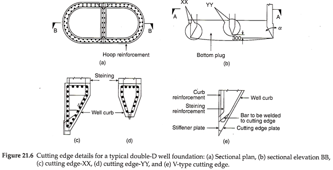
The cutting edge is the lowest part of the well foundation (see Fig. 21.6) and facilitates penetration of the bottom of the well during sinking. The thickness of the cutting edge and the slope angle of the inside edge should be such that it should be sharp enough for easy sinking, and at the same time should not break when penetrating through hard soil or rock. The outer edge of the cutting edge is kept vertical, while the inner edge has a slope of 1H:2V.
3. Steining:
The walls of the well foundation are called steining. Steining earlier used to be constructed with stone or brick, but today it is mostly made of concrete. The steining is also reinforced suitably to withstand the stresses developed during sinking of the well as well as the design stresses. The thickness of steining is generally about one-fourth of the diameter for railway bridges, and one-tenth of the diameter for road bridges.
The thickness of steining is decided on the basis of the following considerations:
i. It should not be too thick so that excessive resistance is avoided during sinking of the well.
ii. It should not be too thin so that it gets damaged either during sinking of the well, or under design loads. The stresses induced in the steining should be within permissible limits under design loads.
iii. The steining should withstand the additional stresses induced, when corrective measures are taken for tilting and shifting of the well.
As per IRC:78, the minimum thickness of well steining for road bridges is 0.5 m. The thickness of steining for road bridges should be determined using –
where ts is the thickness of steining in m, K is the coefficient depending on steining material and well type as shown in Table 21.1, and l is the depth of the well below the top of the well cap or lowest water level (LWL), whichever is more, in m.
4. Bottom Plug:
After sinking of the well is completed to the required depth, the hollow dredge hole at the bottom is concreted up to some depth, which is known as the bottom plug. The bottom plug will enhance the bearing resistance of the well considerably, and provides long-term stability to the well foundation. The surface of the bottom plug is made bowl shaped so as to have an inverted arch action.
The bottom plug is generally designed as a thick plate subjected to uniform bearing pressure under maximum design loads. It has to extend for a minimum height of 30 cm above the top of the well curb. Concreting should be completed at one stretch for the bottom plug. The thickness of the bottom plug maybe determined from Eqs. (21.2) and (21.3).
For circular wells, we have –
where tb is the thickness of the bottom plug, W is the total design load on the base of the well, σf is the flexural strength of the bottom plug material, µ is Poisson’s ratio, D is the diameter of the well, q is the bearing pressure at the base, b is the width of the rectangular well, and a is the ratio of the width to the length of the rectangular well.
5. Sand Filling:
The dredge hole between the top and the bottom plug is filled with sand after sinking is completed, to increase the self-weight of the well, to increase its stability, and to ensure that no tensile bending stresses are developed at the base of the well foundation. Sand filling, however, is not assumed to carry any design loads and the entire design load is assumed to be carried by the steining.
6. Top Plug:
The top plug is of M15 cement concrete of 30 cm thickness above the sand filling.
7. Well Cap:
The reinforced cement concrete (RCC) slab provided at the top of the well is known as the well cap. The well cap provides the required surface for placing the pier or abutment and transfers its loads safely to the well foundation. The bottom of the well cap is generally kept at the LWL. The minimum reinforcement in the well cap is about 80 kgf/m3. The longitudinal bars from well steining, as many in number as possible, should be anchored into the well cap.


